Basic Modelling Concepts
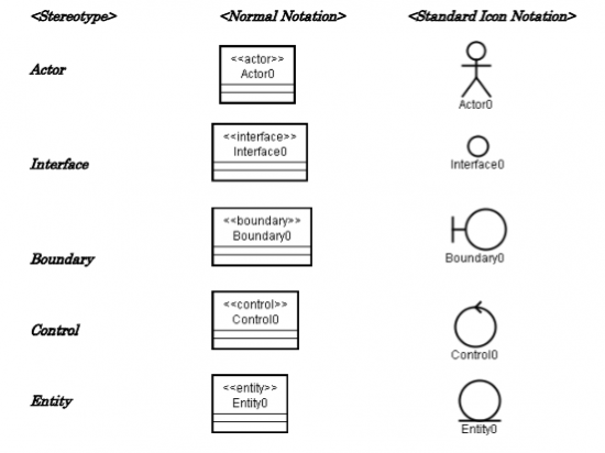
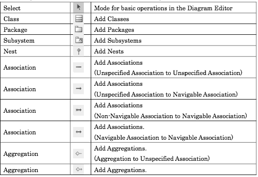
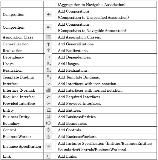
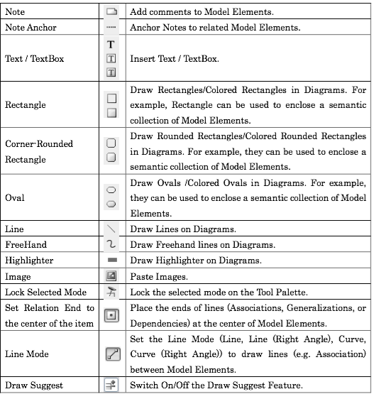
Modelling tools have their own interpretation of how diagrams, icons are used. This webpage tries to give some clues on how this implementation are made.
| Diagram Elements | Sterotypes |
|---|---|
  |
 |
Object Orientation Basic Elements
Basic OO Elements are:
Association
| https://upload.wikimedia.org/wikipedia/en/f/f5/BidirectionalAssociation.png | https://upload.wikimedia.org/wikipedia/en/0/05/UnidirectionalAssociation.png |
|---|---|
| A bidirectional association | Unless otherwise specified, navigation across an association is bidirectional, although it may be limited to just one direction by adorning some end with an arrowhead pointing to the direction of traversal. |
| Description | |
| Association defines a relationship between classes of objects that allows one object instance to cause another to perform an action on its behalf. | |
Aggregation
| https://upload.wikimedia.org/wikipedia/commons/d/d0/Aggregation-Composition3.png |
|---|
| A bidirectional association, first a composition, the second is an aggregation. |
| Description |
| Association defines a relationship between classes of objects that allows one object instance to cause another to perform an action on its behalf. A "uses" B = Aggregation : B exists independently (conceptually) from A.
|
Composition
In Java:
public class Point {
	private float x;
	private float y;

	/**
	 * Constructor
	 * @param x Value for the x-axis.
	 * @param y Value for the y-axis.
	 */
	public Point(float x, float y) {
		this.x = x;
		this.y = y;
	}
...
}
|
width="525"
public class Circle {
	private float radius;
	private Point center;

	/**
	 * Constructor
	 * @param center Instance of class point
	 * @param radius Length of the radius.
	 */
	public Circle(Point center, float radius) {
		this.center = center;
		this.radius = radius;
	}
...
}
|
Design of Class Diagrams
| Ontwerpbeslissingen | Development design decisions |
|---|---|
| Introductie | Introduction |
| De basis vuistregels voor het ontwerpen van Class Diagrams voor beginnende en gevorderde ontwikkelaars. | Basics guidelines for designing Class Diagrams for beginners and experts. |
| - 1 - | |
| Attributen zijn private Getters en Setters toevoegen (Alleen indien nodig) |
Attributes are private Add only the necessary Getters and Setters |
| - 2 - | |
Constructor heeft parameters:
Optioneel extra constructors
|
Constructor has parameters:
Optional extra (alternative) constructors
|
| - 3 - | |
Associatie met lage multipliciteit
Associatie met hoge multipliciteit
|
Association with low multiplicity
Association with high multiplicity
|
| - 4 - | |
Afleidbare informatie
|
Derivable / deductable Information
|
| - 5 - | |
Als een associatie
Introduceer dan een associatie class! |
If an association has
Then Introduce an association class. |
| - 6 - | |
Administratieve verplicting
|
|
| - 7 - | |
Liskov substitutieprincipe:
|
Barbara Liskov:
|
| - 8 - | |
| Programmeer tegen een interface, niet tegen een implementatie | Program against an interface, not against an implementation |
| - 9 - | |
Abstract class of Interface?
|
Abstract class or Interface?
|
Class Visibility
To specify the visibility of a class member (i.e., any attribute or method), these notations must be placed before the member's name:
+ |
Public |
- |
Private |
# |
Protected |
/ |
Derived (can be combined with one of the others) |
~ |
Package |
Sequence Diagrams
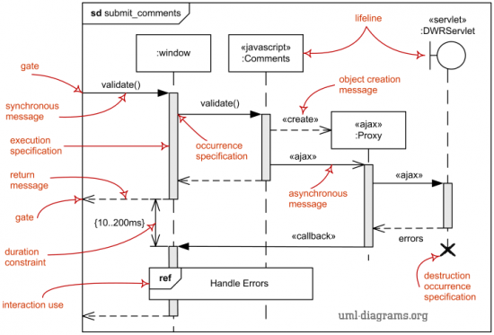
UML Sequence Diagram [1] is the most common kind of interaction diagram, which focuses on the message interchange between a number of lifelines.
Sequence diagram describes an interaction by focusing on the sequence of messages that are exchanged, along with their corresponding occurrence specifications on the lifelines.
The following nodes and edges are typically drawn in a UML sequence diagram: lifeline, execution specification, message, combined fragment, interaction use, state invariant, continuation, destruction occurrence.
Major elements of the sequence diagram are shown on the picture on the right.
- Lifeline is a named element which represents an individual participant in the interaction. While parts and structural features may have multiplicity greater than 1, lifelines represent only one interacting entity ( More... ).
- Syntax:
lifeline-ident ::= [ connectable-element-name [ '[' selector ']' ]] [ ':' class-name ] [ decomposition ] | 'self'
selector ::= expression
decomposition ::= 'ref' interaction-ident [ 'strict' ]
- Syntax:
- Message is a named element that defines one specific kind of communication between lifelines of an interaction. The message specifies not only the kind of communication, but also the sender and the receiver. Sender and receiver are normally two occurrence specifications (points at the ends of messages). ( More... ).
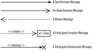
|
| UML Sequence Diagram Arrows |
- Syntax:
message ::= [ attribute '=' ] signal-or-operation-name [ arguments ] [ ':' return-value ] | '*'
arguments ::= '(' [argument [ ',' argument]* ')'
argument ::= [ parameter-name '='] argument-value | attribute '=' out-parameter-name [ ':' argument-value ] | ' -'
- Syntax:
- XX
See also
http://agilemodeling.com/images/style/classDiagramAnalysisVsDesign.gif top
- Agile Modeling, Class Diagrams Guidelines. See example above.
Reference
- ↑ UML Diagrams Sequence Diagrams, Overview of Sequence Diagrams on UML Diagrams
